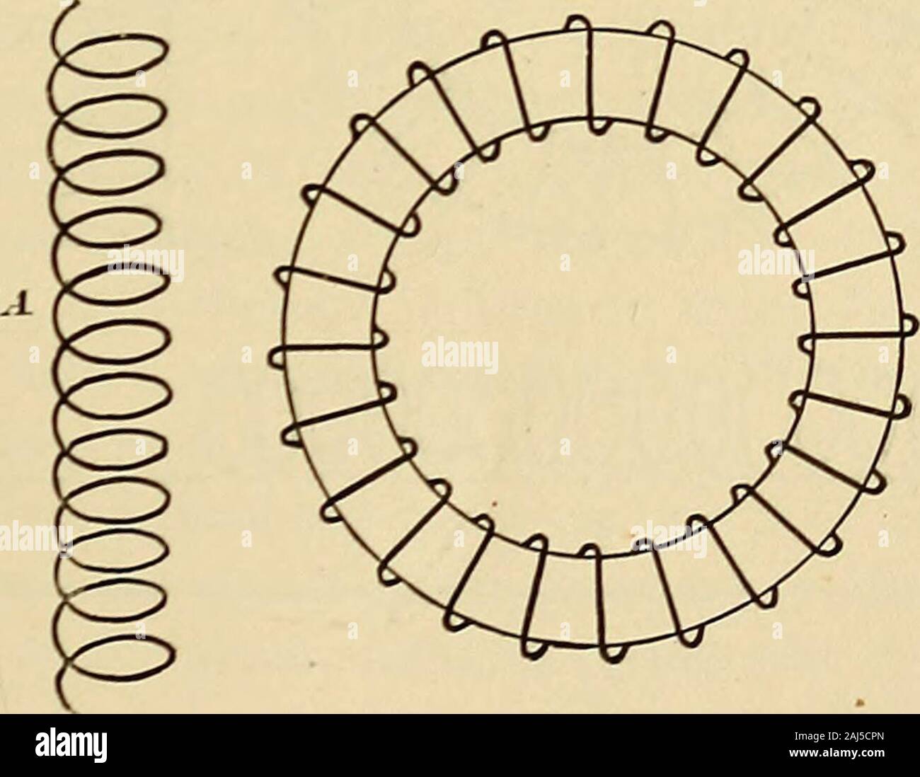
Journal of the Association of Engineering Societies . FIG. 2 the alternating e.m.f. impressed upon the field circuit is a quarter ofa period ahead of the corresponding armature e.m.f., the resultantfield magnetism and armature current will be in phase, or nearlyso, thus yielding a torque which is mainly positive in value. Thismethod is, therefore, equivalent to the use of a two-phase supplycircuit. Although the above-outlined plan effects an increased torqueand, therefore, a greater output, it still fails to obviate the seriousevil of sparking at the commutator. To get around this difficultyit

Image details
Contributor:
The Reading Room / Alamy Stock PhotoImage ID:
2AJ5CPNFile size:
7.2 MB (195.6 KB Compressed download)Releases:
Model - no | Property - noDo I need a release?Dimensions:
1795 x 1393 px | 30.4 x 23.6 cm | 12 x 9.3 inches | 150dpiMore information:
This image is a public domain image, which means either that copyright has expired in the image or the copyright holder has waived their copyright. Alamy charges you a fee for access to the high resolution copy of the image.
This image could have imperfections as it’s either historical or reportage.
Journal of the Association of Engineering Societies . FIG. 2 the alternating e.m.f. impressed upon the field circuit is a quarter ofa period ahead of the corresponding armature e.m.f., the resultantfield magnetism and armature current will be in phase, or nearlyso, thus yielding a torque which is mainly positive in value. Thismethod is, therefore, equivalent to the use of a two-phase supplycircuit. Although the above-outlined plan effects an increased torqueand, therefore, a greater output, it still fails to obviate the seriousevil of sparking at the commutator. To get around this difficultyit is necessary to take the bull by the horns and do away with the. FIG. 3 commutator altogether When this is done, the necessary flow ofcurrent in the armature conductors is effected by utilizing thephenomenon of magneto-electric induction familiarly exemplifiedin the ordinary static transformer. To accomplish this the armatureis wound with a closed coil winding, or even with the ordinary 66 ASSOCIATION OF ENGINEERING SOCIETIES. squirrel-cage arrangement of conductors, and is surrounded by acoil, or group of coils, connected to one of the two supply phases.Thus, as in Fig. 3, the armature is surrounded by two windings, one of which, connected to phase A, furnishes the field magnetism;the other, connected to phase B, carries the energy current, which, after the ordinary transformer action, reappears in the armature. This arrangement is still defective in that it loads the twophases, A and B, unequally, for A carries merely the small mag-netizing current, while B carries the much larger current to be trans-formed into mechanical energy. The next step in