An investigation of the flow of water through submerged orifices and pipes . the earlier experiments were made. The tank used in all the experiments is shown in Pig. 1.It is made in two compartments, I and II, which are sep-arated by a partition containing an opening at C, intowhich nay he fitted the orifice or pipe to he used. Thewater coming from the standpipe enters by a main at A andpasses through the baffle boards at B, finally leaving com-partment II through openings which are regulated by valvesor stoppers. ?or small flows the water was weighed in atank set on scales. For large flows it
Image details
Contributor:
The Reading Room / Alamy Stock PhotoImage ID:
2AXA1WNFile size:
7.1 MB (180.5 KB Compressed download)Releases:
Model - no | Property - noDo I need a release?Dimensions:
1344 x 1858 px | 22.8 x 31.5 cm | 9 x 12.4 inches | 150dpiMore information:
This image is a public domain image, which means either that copyright has expired in the image or the copyright holder has waived their copyright. Alamy charges you a fee for access to the high resolution copy of the image.
This image could have imperfections as it’s either historical or reportage.
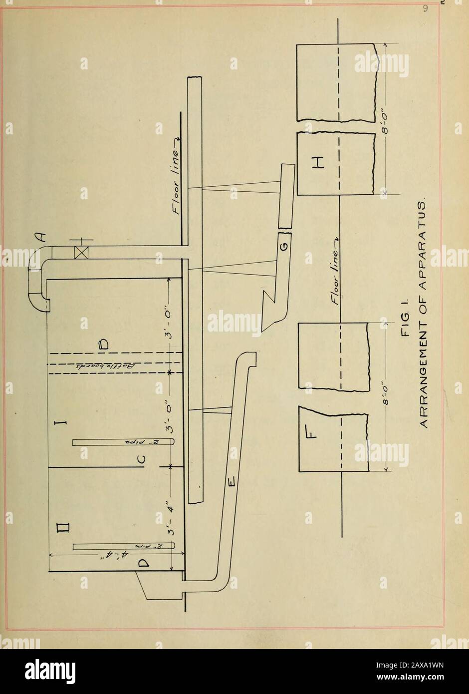
An investigation of the flow of water through submerged orifices and pipes . the earlier experiments were made. The tank used in all the experiments is shown in Pig. 1.It is made in two compartments, I and II, which are sep-arated by a partition containing an opening at C, intowhich nay he fitted the orifice or pipe to he used. Thewater coming from the standpipe enters by a main at A andpasses through the baffle boards at B, finally leaving com-partment II through openings which are regulated by valvesor stoppers. ?or small flows the water was weighed in atank set on scales. For large flows it was measured in thepit F, the water being wasted by means of the movable pipeG into the pit H until the desired rate of flow had beensecured, when it was turned into the measuring pit, wherethe rise was determined by reading a rod. At the bottom ofthis rod there was attached a metal ring which was broughtjust to the surface of the water and the rod was then read. A scale reading to millimeters was used to determinethe head on the orifice or pipe. From either side of the. TABLE I. LIST OF ORIFICES, PIPES, AM) MOUTHPIECES USED. ORIFICES MOUTHPIECES ITo.1. Kind1-in. round .EntranceITo. Angle Ratic17. 5° 1-2 • DischargeNo. Angle30. 5° Ratio1-2 2. 1 l/2-in. Iaj Tf 31. 10° IT 3. 2-in. T CO10 TT 32. 15° tT 4. 4-in. rr CO It 33. 20° TT 5. 6-in. ci. O O I 34. 30° TT 22. /CO TT 35. 45° TT 6. l/2-in. square 60° tT 36. 60° TT 7. 1-in. 24. 10° 1-3 37. 10° 1-3 8. 2-in. 25. 15° IT 38. 15 4-—m. 26. 20° ItII 39. 20° TT 1C. 5 1/2-in. , T 27. 45° TT 40. 45° TT 28. 90° TT 41. 90° TT lx. b—m. x jl/ c—in. 29. 20° 1-4 42. 200 1-4 12. 6—in. x 1—in. COMBINATIONS 13 It/ • 6—in. x 2—in. 43. 6—in. pipe, witft 20°(1-2) entrance and 5° fl—2) discharge. 14. 4—in. triangular. 44. 6-in. pipe, with 20°(1-3) entrance 15. PIPES2-in. x 5 l/2-in. and 15°(1-3) discharge. 17. 6-in. x 22 l/2-in. 11 partition in the tank, a glass tube was lead and placed bythe scale. The d