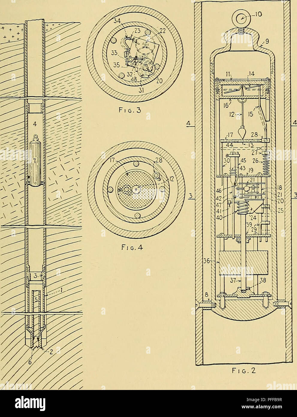
. Deep borehole surveys and problems. Boring. CORE ORIENTATION 89 an inertia motor is adopted. This is a heavy solid lead rotor 36 on a vertical shaft 37 suitably borne in bearings 38 and 39. It is so made that it will lag behind the rotation. FiG.l Plate VI.—Hanna's inertia-rotor apparatus. speed of the drill, thus continuing to rotate some time after the latter, owing to its momentum. On shaft 37 a worm gear 40 is engaged by a toothed projection 41 on a verti- cally movable rod 42 supported in frame 19. As worm gear 40 rotates, with respect to rod 42 and its lug 41, rod 42. Please note that

Image details
Contributor:
Central Historic Books / Alamy Stock PhotoImage ID:
PFFB9RFile size:
7.2 MB (476.9 KB Compressed download)Releases:
Model - no | Property - noDo I need a release?Dimensions:
1381 x 1810 px | 23.4 x 30.6 cm | 9.2 x 12.1 inches | 150dpiMore information:
This image is a public domain image, which means either that copyright has expired in the image or the copyright holder has waived their copyright. Alamy charges you a fee for access to the high resolution copy of the image.
This image could have imperfections as it’s either historical or reportage.
. Deep borehole surveys and problems. Boring. CORE ORIENTATION 89 an inertia motor is adopted. This is a heavy solid lead rotor 36 on a vertical shaft 37 suitably borne in bearings 38 and 39. It is so made that it will lag behind the rotation. FiG.l Plate VI.—Hanna's inertia-rotor apparatus. speed of the drill, thus continuing to rotate some time after the latter, owing to its momentum. On shaft 37 a worm gear 40 is engaged by a toothed projection 41 on a verti- cally movable rod 42 supported in frame 19. As worm gear 40 rotates, with respect to rod 42 and its lug 41, rod 42. Please note that these images are extracted from scanned page images that may have been digitally enhanced for readability - coloration and appearance of these illustrations may not perfectly resemble the original work.. Haddock, M. H. (Marshall Henry). New York, McGraw-Hill