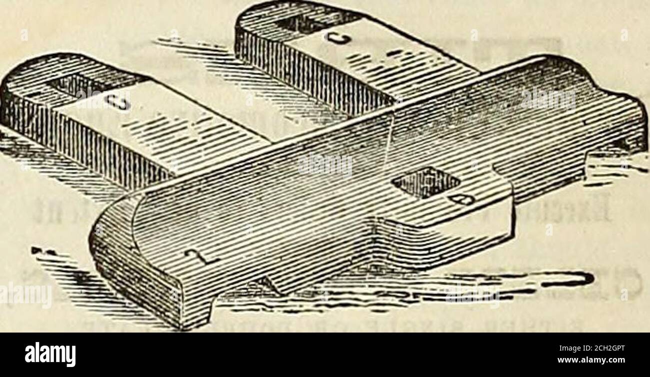
. Railroad record, and journal of commerce, banking, manufactures and statistics . Fig.3 is a perspective view of Joint Rail. Fig. 1 is aview of outside plaie C, whu h is applied on the outer sideof the .joint. It is intended to stand up flush with the faceof the rails, so that it may form an unbroken hearing for thewheels, as they pass the square extremeties nf the rails.This plate may be of such form as to fill up the recess inthe side of the rail, between the head and base, or only tobear against the head and upon the base, leaving an openspace between it and the neck of the rail. The hist
Image details
Contributor:
Reading Room 2020 / Alamy Stock PhotoImage ID:
2CH2GPTFile size:
7.1 MB (364.4 KB Compressed download)Releases:
Model - no | Property - noDo I need a release?Dimensions:
2209 x 1131 px | 37.4 x 19.2 cm | 14.7 x 7.5 inches | 150dpiMore information:
This image is a public domain image, which means either that copyright has expired in the image or the copyright holder has waived their copyright. Alamy charges you a fee for access to the high resolution copy of the image.
This image could have imperfections as it’s either historical or reportage.
. Railroad record, and journal of commerce, banking, manufactures and statistics . Fig.3 is a perspective view of Joint Rail. Fig. 1 is aview of outside plaie C, whu h is applied on the outer sideof the .joint. It is intended to stand up flush with the faceof the rails, so that it may form an unbroken hearing for thewheels, as they pass the square extremeties nf the rails.This plate may be of such form as to fill up the recess inthe side of the rail, between the head and base, or only tobear against the head and upon the base, leaving an openspace between it and the neck of the rail. The hist men-tioned form is the one shown in the drawing. In either casethe lower part of said plate rests partly upon the base of therails, and partly upon the outside tip of the chair, as showninFig.3, . Fig. -Z is a view of inside plate D, which is applied onthe inner side of the joint This plate must fit into the re-cess in the side of the rail, as its upper part can not projectlaterally beyond the hear! of the rails, or it wou!d interferewith the flanges of the wheels. And its lower part. Mice thalower part of plate C, rests partly upon the base of the rails, and partly upon the inside lip of the chair, as shown in themodel. From the inner side of this plate, projects twostrong horizontal tongues C C, which pass through slots inthe ends of the rails, and corresponding ones in the outsideplate C. These tongues rest upon projections, which areprovided on the chair to stand up outside of the plate C, toact as hearings for the tongues C C, and serving, also, inpart, to confine the plate C. The ends of the tongues arefurnished with vertical slots to receive keys, which aredriven through them, and corresponding vertical slots in thechair. The rails and chair are secured to the joint tie b